ARTA Audio Measurement And Analysis Software 1.7.0 | 6.30 MBARTA - program for the impulse response measurement and for real-time spectrum analysis and frequency response measurements. You can read ARTA as Audio Real Time Analysis, and also as Art for Audio
The ARTA program has functions of following measurement systems:
Impulse response measurement system with signal generators: periodic white noise, periodic pink noise, MLS, linear and logarithmic swept-sine.
Dual channel Fourier analyzer with signal generators: white noise, pink noise, periodic white noise and periodic pink noise.
Single channel Fourier analyzer with signal generators: periodic white noise and periodic pink noise.
Spectrum, octave band and THD analyzer with signal generators: sine, two sine, multitone, periodic square and triangle, white noise, pink noise, periodic white noise and periodic pink noise.
Triggered storage scope with spectrum and short-time Fourier analysis.
Two-channel voltage level meter and third octave analyzer
With calibrated microphone, ARTA can be used as a virtual IEC class 1 SPL meter with a real time modes:
Integrating SPL meter with 24 hours data logging,
Octave SPL meter with noise rating (NR, NC, PNC, RC, NCB),
Third octave SPL meter with report of specific loudness, loudness in sones and loudness level in phones.
The ARTA program is also a powerful analyzer of:
Gated frequency response,
Smoothed frequency response (in 1/n-octave bands),
Step response,
Impulse response envelope (ETC – curve),
Cumulative spectral decay waterfall graphs and sonogram,
Burst decay waterfall graphs and sonogram,
Energy decay in reverberant environments,
Room acoustical parameters,
Directivity patterns,
Speech intelligibility measures: MTF, STI, RASTI, %AL.
Link Download:
http://7b0c8e8a.linkbucks.com/
บทความที่ได้รับความนิยม
-
BassBox 6 Pro – A powerful speaker box design program with many professional features, including a design wizard and a huge driver databas...
-
Modification of PC supply AT / ATX to an adjustable 3-15V supply Halfbridge topology supply mod: Everyone sometimes needs a regulated p...
-
Here I bring you wiring diagram of PCs power supply of DTK company. This power supply has ATX design and 200W performance. I was drawed diag...
-
PC POWERSUPPLY OMBYGNINGS PROJEKT Af OZ2CPU Thomas Scherrer Maj 2002 Sๅdan ser den ud ganske ny inden man ๅbner den. Printet ser sๅd...
-
ARTA Audio Measurement And Analysis Software 1.7.0 | 6.30 MB ARTA - program for the impulse response measurement and for real-time spectrum ...
-
Download
-
Microsoft Office 2007 ภาษาไทย Download http://6acd8c12.linkbucks.com/ http://64b84515.linkbucks.com/ http://34c75fb7.linkbucks.com/ h...
-
Computer power supplies cost around US$30,but lab power supplies can run you $100 or more! By converting the cheap (free) ATX power supplies...
-
การเปิดใช้งาน cookies ใน Internet Explorer ขั้นตอนการเปิดใช้งานตาม browser จากเว็ป timeanddate.com: Internet Explorer 9.0 Internet Explore...
วันพุธที่ 27 เมษายน พ.ศ. 2554
BassBox 6 Pro with X·over 3 Pro

BassBox 6 Pro – A powerful speaker box design program with many professional features, including a design wizard and a huge driver database with the specs for thousands of drivers. Also includes a beautiful 364-page printed manual and an extensive on-screen manual with tutorials and sample designs.
X•over 3 Pro – An easy-to-use passive circuit design program for 2-way and 3-way crossover networks, low-pass, band-pass and high-pass filters, impedance EQ networks and L-pads. Includes a huge driver database like BassBox Pro and a beautiful 243-page printed manual and extensive on-screen manual.
This is the home of BassBox, our famous speaker enclosure design program. We offer two versions: BassBox Pro and BassBox Lite. They help the speaker designer determine a good box volume and, if vented, how it should be tuned. This is controlled primarily by the desired bass response and both programs focus on that aspect of design. They do not model high-frequency or sealed-back drivers like tweeters. For that, we offer X•over Pro, our third program. It models two-way and three-way speakers to help you design a passive crossover network for them. It can import box designs from BassBox Pro and Lite and add to them the response of a midrange driver and tweeter to estimate the response of a full-range speaker.
Home Page - http://www.ht-audio.com/
Download: 40.82 MB
Mirror:
Password: www.dl4all.com
วันเสาร์ที่ 23 เมษายน พ.ศ. 2554
200W ATX PC POWER SUPPLY
Here I bring you wiring diagram of PCs power supply of DTK company. This power supply has ATX design and 200W performance. I was drawed diagram, when I repaired this power supply.
This power supply circuit uses chip TL494. Similar circuit is used in the most power supplies with output power about 200W.Device use push-pull transistor circuit with regulation of output voltage.
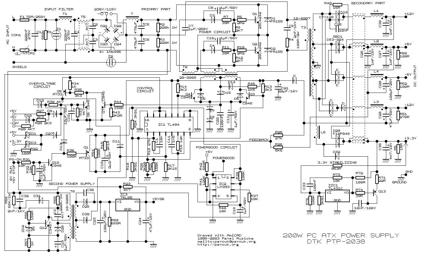 Line voltage goes through input filter circuit (C1, R1, T1, C4, T5) to the bridge rectifier. When voltage is switched from 230V to 115V, then rectifier works like a doubler. Varistors Z1 and Z2 have overvoltage protect function on the line input.
Thermistor NTCR1 limits input current until capacitors C5 and C6 are charged. R2 and R3 are only for discharge capacitors after disconnecting power supply. When power supply is connected to the line voltage, then at first are charged capacitors C5 and C6 together for about 300V.
Then take a run secondary power supply controlled by transistor Q12 and on his output will be voltage. Behind the voltage regulator IC3 will be voltage 5V, which goes in to the motherboard and it is necessary for turn-on logic and for "Wake on something" functions.
Next unstabilized voltage goes through diode D30 to the main control chip IC1 and control transistors Q3 and Q4. When main power supply is running, then this voltage goes from +12V output through diode D.
In a normal operation is power supply controlled by IC1. When transistors Q1 and Q2 are closed, then Q3 and Q4 are opened. When we want to open one from power transistors (Q1, Q2), then we have to close his exciting transistor (Q3, Q4). Current goes via R46 and D14 and one winding T2. This current excite voltage on base of power transistor and due to positive feedback transistor goes quickly to saturation. When the impulse is finished, then both exciting transistors goes to open. Positive feedback dissapears and overshoot on the exciting winding quickly closes power transistor. After it is process repetead with second transistor. Transistors Q1 and Q2 alternately connects one end of primary winding to positive or negative voltage. Power branch goes from emitor of Q1 (collector Q2) through the third winding of exciting transformer T2. Next throug primary winding of main transformer T3 and capacitor C7 to the virtual center of supply voltage.
This voltage is rated from voltage before coil, pulse-width and duration cycle. On the output behind the rectifier diodes is a common coil for all voltages. When we keep direction of windings and winding number corresponding to output voltages, then coil works like a transformer and we have compensation for irregular load of individual voltages.
In a common practise are voltage deviations to 10% from rated value. From the internal 5-V reference regulator (pin 14 IC1) goes reference voltage through the voltage divider R24/R19 to inverting input(pin 2) of error amplifier. From the output of power supply comes voltage through divider R25,R26/R20,R21 to the non inverting input (pin 1). Feedback C1, R18 provides stability of regulator. Voltage from error amplifier is compared to the ramp voltage across capacitor C11.
When the output voltage is decreased, then voltage on the error amplifier is toodecreased. Exciting pulse is longer, power transistors Q1 and Q2 are longer opened, width of pulse before output coil is grater and output power is increased. The second error amplifier is blocked by voltage on the pin 15 IC1.
For example when I by mistake short-circuit -5V with +5V, then positive voltage goes across D10, R28, D9 to the base Q6. This transistor is now opened and opens Q5. +5V from pin 14 IC1 comes across diode D11 to the pin 4 IC1 and power supply is blocked. Beyond that goes voltage again to base Q6. Power supply is still blocked, until he is disconnected from power line input.
This power supply circuit uses chip TL494. Similar circuit is used in the most power supplies with output power about 200W.Device use push-pull transistor circuit with regulation of output voltage.
 Line voltage goes through input filter circuit (C1, R1, T1, C4, T5) to the bridge rectifier. When voltage is switched from 230V to 115V, then rectifier works like a doubler. Varistors Z1 and Z2 have overvoltage protect function on the line input.
Thermistor NTCR1 limits input current until capacitors C5 and C6 are charged. R2 and R3 are only for discharge capacitors after disconnecting power supply. When power supply is connected to the line voltage, then at first are charged capacitors C5 and C6 together for about 300V.
Then take a run secondary power supply controlled by transistor Q12 and on his output will be voltage. Behind the voltage regulator IC3 will be voltage 5V, which goes in to the motherboard and it is necessary for turn-on logic and for "Wake on something" functions.
Next unstabilized voltage goes through diode D30 to the main control chip IC1 and control transistors Q3 and Q4. When main power supply is running, then this voltage goes from +12V output through diode D.
Stand-By mode
In stand-by mode is main power supply blocked by positive voltage on the PS-ON pin through resistor R23 from secondary power supply. Because of this voltage is opened transistor Q10, which opens Q1, which applies reference voltage +5V from pin 14 IO1 to pin 4 IO1. Switched circuit is totally blocked. Tranzistors Q3 and Q4 are both opened and short-circuit winding of auxiliary transformer T2.Due to short-circuit is no voltage on the power circuit. By voltage on pin 4 we can drive maximum pulse-width on the IO1 output. Zero voltage means the highest pulse-width. +5V means that pulse disappear.Now we can explain function of running power supply.
Somebody pushes the power button on computer. Motheboard logic put to ground input pin PS-ON. Transistor Q10 closes and next Q1 closes. Capacitor C15 begins his charging through R15 and on the pin 4 IC1 begins decrease voltage to zero thanks to R17. Due to this voltage is maximum pulse-width continuosly increased and main power supply smoothly goes run.In a normal operation is power supply controlled by IC1. When transistors Q1 and Q2 are closed, then Q3 and Q4 are opened. When we want to open one from power transistors (Q1, Q2), then we have to close his exciting transistor (Q3, Q4). Current goes via R46 and D14 and one winding T2. This current excite voltage on base of power transistor and due to positive feedback transistor goes quickly to saturation. When the impulse is finished, then both exciting transistors goes to open. Positive feedback dissapears and overshoot on the exciting winding quickly closes power transistor. After it is process repetead with second transistor. Transistors Q1 and Q2 alternately connects one end of primary winding to positive or negative voltage. Power branch goes from emitor of Q1 (collector Q2) through the third winding of exciting transformer T2. Next throug primary winding of main transformer T3 and capacitor C7 to the virtual center of supply voltage.
Output voltage stabilisation
Output voltages +5V and +12V are measured by R25 and R26 and their output goes to the IC1. Other voltages are not stabilised and they are justified by winding number and diode polarity. On the output is necessary reactance coil due to high frequency interference.This voltage is rated from voltage before coil, pulse-width and duration cycle. On the output behind the rectifier diodes is a common coil for all voltages. When we keep direction of windings and winding number corresponding to output voltages, then coil works like a transformer and we have compensation for irregular load of individual voltages.
In a common practise are voltage deviations to 10% from rated value. From the internal 5-V reference regulator (pin 14 IC1) goes reference voltage through the voltage divider R24/R19 to inverting input(pin 2) of error amplifier. From the output of power supply comes voltage through divider R25,R26/R20,R21 to the non inverting input (pin 1). Feedback C1, R18 provides stability of regulator. Voltage from error amplifier is compared to the ramp voltage across capacitor C11.
When the output voltage is decreased, then voltage on the error amplifier is toodecreased. Exciting pulse is longer, power transistors Q1 and Q2 are longer opened, width of pulse before output coil is grater and output power is increased. The second error amplifier is blocked by voltage on the pin 15 IC1.
PowerGood
Mainboard needs "PowerGood" signal. When all output voltages goes to stable, then PowerGood signal goes to +5V (logical one). PowerGood signal is usually connected to the RESET signal.+3.3V Voltage stabilisation
Look at circuit connected to output voltage +3.3V. This circuit makes additional voltage stabilisation due to loss of voltage on cables. There are one auxiliary wire from connector for measure 3.3V voltage on motherboard.Overvoltage circuit
This circuit is composed from Q5, Q6 and many discrete components. Circuit guards all of output voltages and when the some limit is exceeded, power supply is stopped.For example when I by mistake short-circuit -5V with +5V, then positive voltage goes across D10, R28, D9 to the base Q6. This transistor is now opened and opens Q5. +5V from pin 14 IC1 comes across diode D11 to the pin 4 IC1 and power supply is blocked. Beyond that goes voltage again to base Q6. Power supply is still blocked, until he is disconnected from power line input.
Links
- http://www.belza.cz/swmodeps/compow1.htm (Czech language only)
- http://www.belza.cz/swmodeps/compow2.htm (Czech language only)
- http://www.epanorama.net/links/psu_computer.html Computer Power Supply Page
- http://www.webx.dk/oz2cpu/radios/psu-pc1.htm Power supply modification
ATX Power Connector
| Pin | Signal | Color 1 | Color 2 | Pin | Signal | Color 1 | Color 2 |
|---|---|---|---|---|---|---|---|
| 1 | 3.3V | orange | violet | 11 | 3.3V | orange | violet |
| 2 | 3.3V | orange | violet | 12 | -12V | blue | blue |
| 3 | GND | black | black | 13 | GND | black | black |
| 4 | 5V | red | red | 14 | PS_ON | green | grey |
| 5 | GND | black | black | 15 | GND | black | black |
| 6 | 5V | red | red | 16 | GND | black | black |
| 7 | GND | black | black | 17 | GND | black | black |
| 8 | PW_OK | grey | orange | 18 | -5V | white | white |
| 9 | 5V_SB | violet | brown | 19 | 5V | red | red |
| 10 | 12V | yellow | yellow | 20 | 5V | red | red |
Modification of PC supply AT / ATX to an adjustable 3-15V supply
Modification of PC supply AT / ATX to an adjustable 3-15V supply Halfbridge topology supply mod:
Everyone sometimes needs a regulated power supply. Laboratory power supplies are expensive and therefore we usually use what is available. As a small voltage supply with a large current we the most frequently use AT or ATX supplies from computers. Their disadvantage is not truly stabilized voltage and often need to load both the two main outputs (5 and 12V) of approximately the same power. Therefore, I present a simple modification of the PC power supply of type AT and ATX to a regulated source of 3 - 15V with the true stabilization and the current corresponding to the original 12V output. Feedback stabilization is connected to 1 outlet circuit TL494 (Or its equivalent, KA7500, KIA494, DBL494 - the same circuit is used in 90% of common supplies). The reference voltage is 2.5 V (ie circuit regulates the output voltage so that voltage divider created just 2.5 V). Originally stabilization is linked to outputs 5 and 12V and works well only when you equally load both outputs. After this modification the feedback is associated with the 12V output only. Potentiometer regulates the voltage in the range of 3 - 15V. Potentiometer can be replaced by resistor to set constant voltage if needed. The ATX supply fan can be connected to the 5VSB so that it does not affect regulation.
AT or ATX PC power supply outputs
Yellow ... 12V
Red ... 5V
Black ... 0V (GND or COM)
Green ... Standby power. This is only in case of ATX. Connect it to black (0V) tu turn the supply on.
WARNING !!!
There's a dangerous lethal line voltage inside the power supply. Capacitors can remain charged even after shutdown. Inappropriately modified source can be dangerous. You do everything on your own risk.
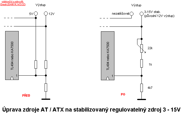
Schematic of the modification of PC AT or ATX supply to a adjustable source of stabilized 3-15V
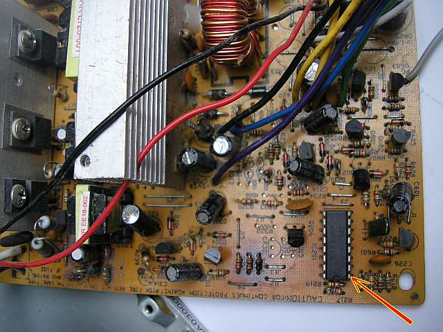
Pin 1 of xx494
Forward converter supply (single MOSFET) mod
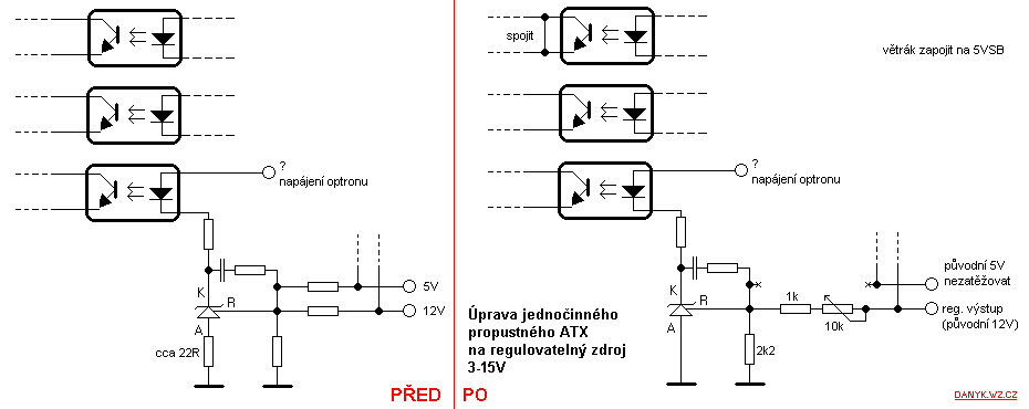
Schematic of modification of the single MOSFET forward converter ATX PC-supply into an adjustable stabilised power supply of 3-15V
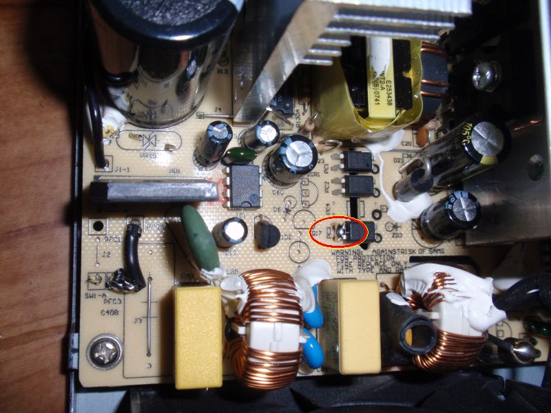
Optocoupler, which turn on the supply from the standby mode. Short the emitter and collector together (they are on primary side).
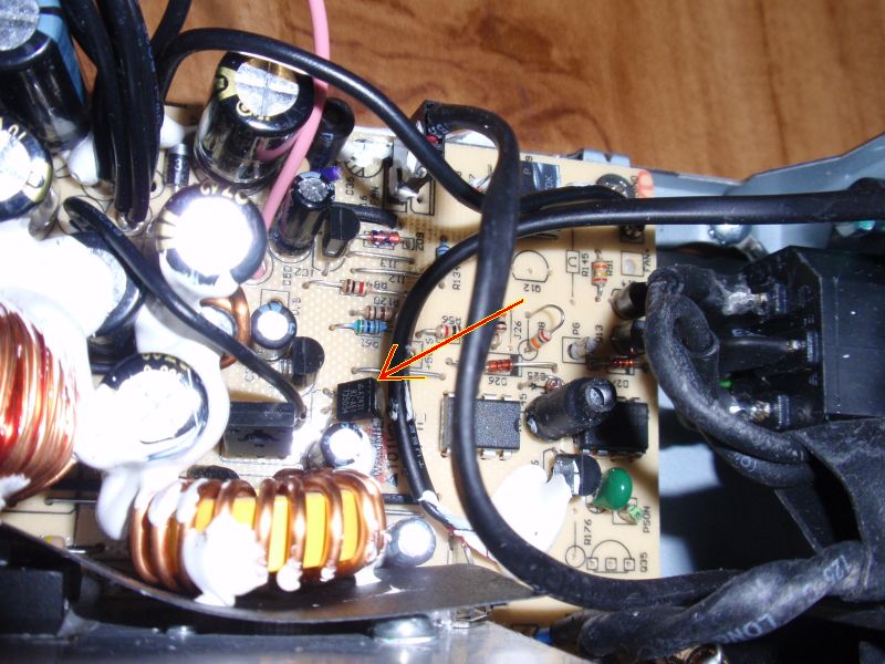
TL431 integrated circuit (in a TO92 packages).
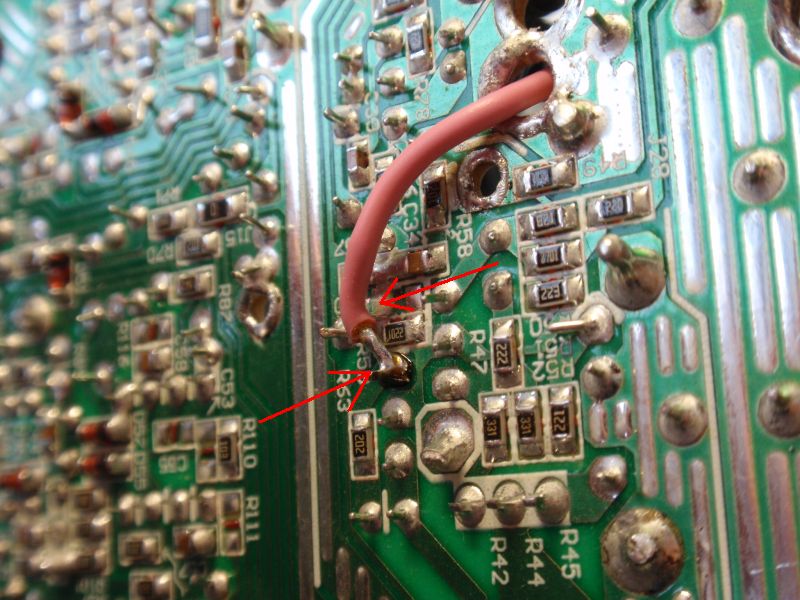
The board under TL431. Removed resistor to 5V, connected wire to regulation.
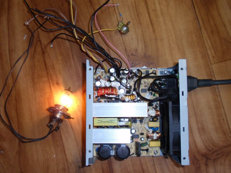
Modified supply
Everyone sometimes needs a regulated power supply. Laboratory power supplies are expensive and therefore we usually use what is available. As a small voltage supply with a large current we the most frequently use AT or ATX supplies from computers. Their disadvantage is not truly stabilized voltage and often need to load both the two main outputs (5 and 12V) of approximately the same power. Therefore, I present a simple modification of the PC power supply of type AT and ATX to a regulated source of 3 - 15V with the true stabilization and the current corresponding to the original 12V output. Feedback stabilization is connected to 1 outlet circuit TL494 (Or its equivalent, KA7500, KIA494, DBL494 - the same circuit is used in 90% of common supplies). The reference voltage is 2.5 V (ie circuit regulates the output voltage so that voltage divider created just 2.5 V). Originally stabilization is linked to outputs 5 and 12V and works well only when you equally load both outputs. After this modification the feedback is associated with the 12V output only. Potentiometer regulates the voltage in the range of 3 - 15V. Potentiometer can be replaced by resistor to set constant voltage if needed. The ATX supply fan can be connected to the 5VSB so that it does not affect regulation.
AT or ATX PC power supply outputs
Yellow ... 12V
Red ... 5V
Black ... 0V (GND or COM)
Green ... Standby power. This is only in case of ATX. Connect it to black (0V) tu turn the supply on.
WARNING !!!
There's a dangerous lethal line voltage inside the power supply. Capacitors can remain charged even after shutdown. Inappropriately modified source can be dangerous. You do everything on your own risk.

Schematic of the modification of PC AT or ATX supply to a adjustable source of stabilized 3-15V

Pin 1 of xx494
Forward converter supply (single MOSFET) mod

Schematic of modification of the single MOSFET forward converter ATX PC-supply into an adjustable stabilised power supply of 3-15V

Optocoupler, which turn on the supply from the standby mode. Short the emitter and collector together (they are on primary side).

TL431 integrated circuit (in a TO92 packages).

The board under TL431. Removed resistor to 5V, connected wire to regulation.

Modified supply
PC POWERSUPPLY OMBYGNINGS PROJEKT
PC POWERSUPPLY OMBYGNINGS PROJEKT
Af OZ2CPU Thomas Scherrer Maj 2002

Sๅdan ser den ud ganske ny inden man ๅbner den.

Printet ser sๅdan ud.
Type: Switching Power Supply 400 Watt ATX PFC
Model: LC-A400ATX PFC
ลrhus:
Pris: 189 kr +porto mv
Varenummer: 30514
Butik: http://www.compumail.dk/
K๘benhavn:
Pris: 235 Kr +porto mv
Varenummer: Desvๆre ikke at finde
Butik: http://www.hkautomation.dk/
KLIK HER FOR 14V 18A OMBYGNINGS BESKRIVELSEN
Originale Specifikationer pๅ psu:
+3.3V 24A
+5V 35A
+12V 12A
+5VSB 2A
-5V 500mA
-12V 800mA
Print kort info: ASIC ATX Ver:1.0B
Ensretter dobbelt dioder:
MOSPEC S30D40C 30A 40V (til 5V out)
MOSPEC SB1640 16A 40V (til 3.3V out)
BYQ28E200 10A 200V (til 12V out)
Controller IC hedder DR0183 og har 16 ben

Her ses udgangs delen.

Her er hele lodde siden inden ombygning.

Power Factor Corrector spolen pๅ 52mH fylder godt i lๅget.

T1 Trafo vindings tal og ben forbindelser

T2 Trafo vindings tal og ben forbindelser

T3 Trafo vindings tal og ben forbindelser
DIAGRAMMER OVER HELE MASKINEN FุR OMBYGNING:
H๘jre klik pๅ billederne. Gem. Print ud, med et grafik program for bedre opl๘sning..

Input filter printet.

Hi-volt primๆr delen.

Udgangs delen, ensrettere og filtre.

Regulerings delen med controlleren.
วันศุกร์ที่ 22 เมษายน พ.ศ. 2554
Building an affordable power supply
Computer power supplies cost around US$30,but lab power supplies can run you $100 or more! By converting the cheap (free) ATX power supplies that can be found in any discarded computer, you can get a phenomenal lab power supply with huge current outputs, short circuit protection, and reasonably tight voltage regulation on the 5V line.
On most PSUs, the other lines are unregulated.

Steps
On most PSUs, the other lines are unregulated.

Steps
- 1Unplug the power cord from the back of the computer. "Harvest" a power supply from a computer by opening up the case of the computer, locating the gray box that is the power supply unit, tracing the wires from the power supply to the boards and devices and disconnecting all the cables by unplugging them.
- 2Remove the screws (typically 4) that attach the power supply to the computer case and remove the power supply.
- 3Cut off the connectors (leave a few inches of wire on the connectors so that you can use them later on for other projects).
- 4Discharge the power supply by letting it sit unconnected for a few days. Some people suggest attaching a 10 ohm resistor between a black and red wire (from the power cables on the output side), however this is only guaranteed to drain the low voltage capacitors on the output - which aren't dangerous to begin with! It could leave the high-voltage capacitors charged, resulting in a potentially dangerous - or even lethal - situation.
- 5
Gather the parts you need: binding posts (terminals), a LED with a current-limiting resistor, a switch (optional), a power resistor (10 ohm, 10W or greater wattage, see Tips), and heat shrink tubing. - 6Open up the power supply unit by removing the screws connecting the top and the bottom of the PSU case.
- 7Bundle wires of the same colors together. If you have wires not listed here (brown, etc), see the Tips.
The color code for the wires is: Red = +5V, Black = Ground (0V), White = -5V, Yellow = +12V, Blue = -12V, Orange = +3.3V, Purple = +5V Standby (not used), Gray = power is on (output), and Green = Turn DC on (input). - 8
Drill holes in a free area of the power supply case by marking the center of the holes with a nail and a tap from the hammer. Use a Dremel to drill the starting holes followed by a hand reamer to enlarge the holes until they are the right size by test fitting the binding posts. Also, drill holes for the power ON LED and a Power switch (optional). - 9
Screw the binding posts into their corresponding holes and attach the nut on the back. - 10Connect all the pieces together.
- Connect one of the red wires to the power resistor, all the remaining red wires to the red binding posts;
- Connect one of the black wires to the other end of the power resistor, one black wire to a resistor (330 ohm) attached to the cathode (shorter lead) of the LED, one black wire to the DC-On switch, all the remaining black wires to the black binding post;
- Connect the white to the -5V binding post, yellow to the +12V binding post, the blue to the -12V binding post, the gray to the anode (longer lead) of the LED;
Note that some power supplies may have either a gray or brown wire to represent "power good"/"power ok". (Most pSU's have a smaller orange wire that is used for sensing-- 3.3V- and this wire is usually paired at the connector to another orange wire. Make sure this wire is connected to the other orange wires, otherwise your lab power supply won't stay on.) This wire should be connected to either an orange wire (+3.3V) or a red wire (+5V) for the power supply to function. When in doubt, try the lower voltage first (+3.3V). If a power supply is non ATX or AT compliant, it may have its own color scheme. If yours looks different that the pictures shown here, make sure you reference the position of the wires attached to the AT/ATX connector rather than the colors.- Connect the green wire to the other terminal on the switch.
- Make sure that the soldered ends are insulated in heatshrink tubing.
- Organize the wires with a electrical tape or zip-ties.
- 11
Check for loose connections by gently tugging on them. Inspect for bare wire, and cover it to prevent a short circuit. Put a drop of super-glue to stick the LED to its hole. Put the cover back on. - 12
Plug the power cord into the back and into an AC socket. Flip the main switch on the PSU. Check to see if the LED light comes on. If it has not, then power up by flipping the switch you placed on the front. Plug in a 12V bulb into the different sockets to see if the PSU works, also check with a digital voltmeter. It should look good and work like a charm!
การเปิดใช้งาน cookies ใน Internet Explorer
การเปิดใช้งาน cookies ใน Internet Explorer
ขั้นตอนการเปิดใช้งานตาม browser จากเว็ป timeanddate.com:Internet Explorer 9.0
Internet Explorer 8.0
Internet Explorer 7.0
Internet Explorer 6.0
Internet Explorer 5.0/5.5
TIP: หากตุณไม่ร฿ว่าคุณใช้ browser รุ่นใด ให้กดที่ Help->About Internet Explorer (Note: เมนูช่วยเหลือ กดที่ไอคอน "?" ในInternet Explorer 8 ).
Internet Explorer 9.0
- กดที่รูปเพืองด้านบนขวาของ browser.
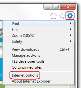
- เลือก "Internet Options".
- เลืกไปที่ "Privacy" tab.
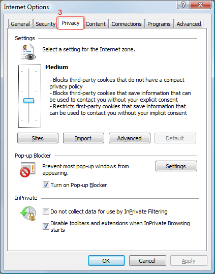
- You now have two options depending on how much you want to restrict cookies:
Automatic cookie handling
- Set the slider to "Medium".
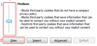
- This should be enough to enable cookies on timeanddate.com, but it is recommended to add timeanddate.com to the Sites list. To do this, click "Sites".
- Enter "timeanddate.com" in the "Address of the website:" input.
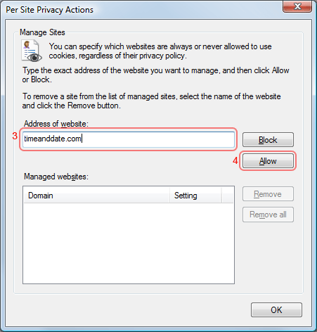
- Click "Allow".
- Click "OK".
- Click "OK".
Restrict to selective sites
NOTE: using this method you will have to enable cookies for every site you need them on.
- Set the slider to "High".
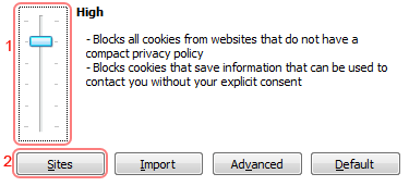
- Click "Sites".
- Enter "timeanddate.com" in the "Address of the website:" input.

- Click "Allow".
- Click "OK".
- Click "OK".
- Set the slider to "Medium".
Internet Explorer 8.0
- Click on the "Tools" menu in Internet Explorer.
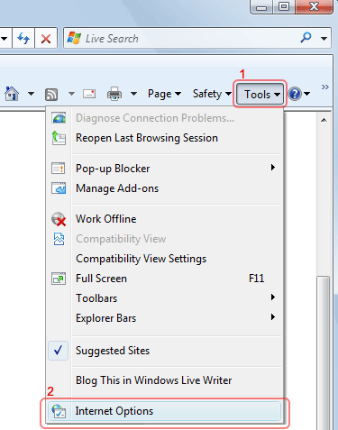
- Click "Internet Options".
- Change to the "Privacy" tab.

- You now have two options depending on how much you want to restrict cookies:
Automatic cookie handling
- Set the slider to "Medium".

- This should be enough to enable cookies on timeanddate.com, but it is recommended to add timeanddate.com to the Sites list. To do this, click "Sites".
- Enter "timeanddate.com" in the "Address of the website:" input.

- Click "Allow".
- Click "OK".
- Click "OK".
Restrict to selective sites
NOTE: using this method you will have to enable cookies for every site you need them on.
- Set the slider to "High".

- Click "Sites".
- Enter "timeanddate.com" in the "Address of the website:" input.

- Click "Allow".
- Click "OK".
- Click "OK".
- Set the slider to "Medium".
Internet Explorer 7.0
- Click on the Tools popup-menu in Internet Explorer.
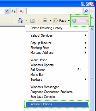
- Click on the Internet Options item in the menu - a new window opens.
- Click on the Privacy tab near the top of the window.
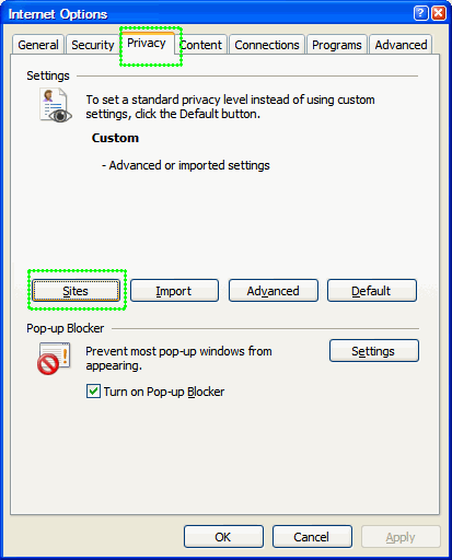
- Click on the Sites button - another window opens.
- Enter timeanddate.com in the text field and then click Allow. timeanddate.com will appear in the "Managed websites" list below with a Setting of Allowed.
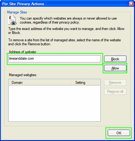
- Save changes by clicking Ok in each window and go to one of the configuration pages again.
Internet Explorer 6.0
- Click on the Tools-menu in Internet Explorer.
- Click on the Internet Options item in the menu - a new window opens.
- Click on the Privacy tab near the top of the window. (See image below)
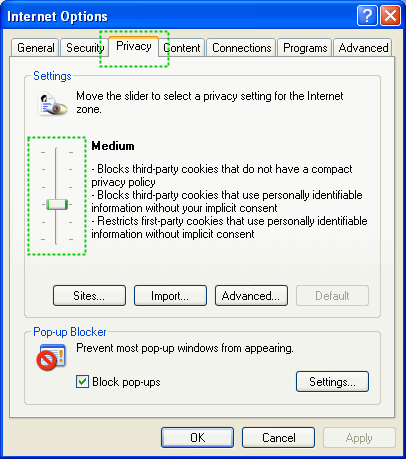
- Move the slider (See image) so that is on one of the levels below Medium High (including Medium, Low, Accept All Cookies.
- Save changes by clicking Ok and go to one of the configuration pages again.
Internet Explorer 5.0/5.5
- Click on the Tools-menu in Internet Explorer.
- Click on the Internet Options item in the menu - a new window opens.
- Click on the Security tab near the top of the window.
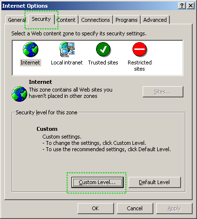
- Click on the Custom Level... button near the bottom of the window.
- Scroll down to Cookies in the new dialog, and set both "Allow cookies that are stored on your computer" and "Allow per-session cookies to Enable.
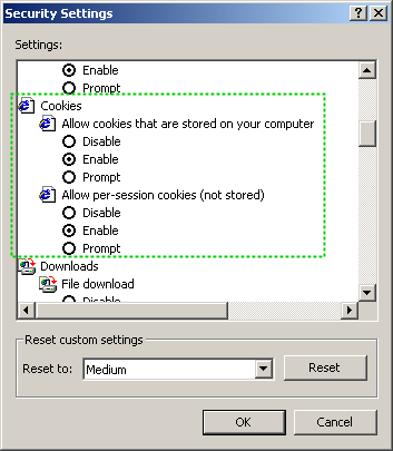
- Save changes by clicking Ok in each dialog and go to one of the configuration pages again.
- Cookies in Mozilla Firefox
- Cookies in Opera
- Cookies in Netscape
- Cookies in Chrome
- Cookies in Safari
- Cookies in other browsers
- Site Configuration – set country, language, time/date formats, time zone and more
- Personal World Clock – Setup
Enabling cookies in other browsers
Customization pages
Microsoft Office 2007 ภาษาไทย
Microsoft Office 2007 ภาษาไทย

Download
http://6acd8c12.linkbucks.com/
http://64b84515.linkbucks.com/
http://34c75fb7.linkbucks.com/
http://7fb2dccc.linkbucks.com/
http://f35e44c7.linkbucks.com/
http://c0b74543.linkbucks.com/
http://b70911db.linkbucks.com/
http://717ea792.linkbucks.com/
http://a7ce404a.linkbucks.com/
http://e17a65b0.linkbucks.com/
http://9dec6136.linkbucks.com/
http://12a25601.linkbucks.com/
http://38a196f5.linkbucks.com/
Pass : Parasetamon
Credit : ParaSetaMon
วันพฤหัสบดีที่ 21 เมษายน พ.ศ. 2554
สมัครสมาชิก:
ความคิดเห็น (Atom)


